In the world of contactless identification, RFID distance—the space between a reader and a tag that still allows successful communication—is one of the most misunderstood performance metrics. Many users purchase RFID systems expecting to achieve the long reading ranges advertised in datasheets, only to discover that in real-world environments, the distance is significantly shorter. This gap between expectation and reality can cause frustration, wasted investment, and even project failure. But in most cases, it’s not a problem with the RFID technology itself—it’s about understanding what limits RFID distance and how to optimize it.
1. What Determines RFID Reading Distance?
Before identifying what’s going wrong, it helps to understand the basic technical factors that define how far an RFID tag can be read.
1.1 Frequency Band
Different RFID systems operate at different frequencies:
- LF (125–134 kHz): Short range (a few centimeters), ideal for access control and animal tagging.
- HF (13.56 MHz): Range of up to 1 meter, common in contactless smart cards.
- UHF (860–960 MHz): Long range (up to 12 meters or more), widely used in logistics, retail, and vehicle access.
1.2 Reader Power and Antenna Design
Reader transmission power, antenna gain, and orientation play critical roles. Even small misalignments between tag and reader antennas can reduce range dramatically. In addition, longer coaxial cables or poor-quality connectors introduce signal loss that eats into available power.
1.3 Environmental Conditions
RFID signals are electromagnetic waves. Like any wave, they can be absorbed, reflected, or scattered by materials in the environment. Metal surfaces, water, and even humidity can all influence RFID distance in unpredictable ways.
2. Common Reasons Why RFID Distance Falls Short
When the measured RFID distance is consistently below expectations, the cause can almost always be traced back to one or more of the following real-world factors that degrade the radio frequency link.

2.1 Environmental Interference
The environment is the single biggest variable in an RFID deployment. Radio waves are easily absorbed, reflected, or scattered by common materials, severely limiting the effective range.
- Metal: Metal is the nemesis of UHF RFID. It reflects radio waves, creating multipath interference that can cause signal cancellation or, if the tag is placed directly on it, detune the tag’s antenna, rendering it unreadable. In a warehouse setting, metallic racks, shelving, and even metal-framed doors can drastically reduce the effective UHF RFID distance.
- Water and Liquids: Water is highly absorptive of microwave frequencies, including UHF. Tags placed on or near items with high water content (e.g., produce, beverages) will experience significant signal attenuation.
- Electromagnetic Noise: Other electronic devices, such as Wi-Fi routers, fluorescent lights, and machinery, can emit electromagnetic noise in the same frequency band, masking the weak return signal from the tag.
2.2 Tag Orientation and Placement
A passive RFID tag acts like a miniature antenna. For maximum energy transfer, the tag’s antenna must be correctly aligned with the reader’s antenna.
- Polarization Mismatch: Most UHF reader antennas are linearly polarized (either horizontal or vertical). If the tag’s antenna is oriented 90 degrees to the reader’s polarization, the signal transfer can drop to near zero. This is known as polarization mismatch. In real-world scenarios, tags are often randomly oriented, leading to inconsistent reads.
- Placement on Materials: The material the tag is affixed to can detune the tag’s antenna. A tag designed for air-mounting will perform poorly when placed directly on metal or high-dielectric materials like plastic or wood, as the material changes the electrical properties of the antenna.
2.3 Reader and Antenna Configuration
Even with the best tags and a clean environment, poor configuration can cripple the system’s performance.
- Insufficient Power and Tuning: The reader’s output power must be correctly set, often to the maximum allowed by local regulations. Furthermore, the antenna must be properly tuned to the reader and the operating frequency. An improperly tuned antenna will reflect power back to the reader instead of radiating it, wasting energy and reducing range.
- Cable Losses and Impedance Matching: Every component in the RF chain—from the reader’s output port, through the coaxial cable, to the antenna—introduces signal loss. Long or low-quality cables can introduce significant attenuation. Impedance matching (ensuring the reader, cable, and antenna all have the same characteristic impedance, typically 50 ohms) is essential to prevent standing waves and power reflection. A mismatch here can dramatically shorten the effective range.
- Antenna Mounting and Coverage: The physical mounting of the antenna determines the coverage area. If the antenna is mounted too high, too low, or aimed incorrectly, the RF field may not adequately cover the area where tags are expected to pass, leading to missed reads and a perceived short range.
2.4 Regulatory Power Limits
A factor that often surprises users is the legal restriction on transmission power.
- Regional Regulations: Governments regulate the maximum power (Effective Isotropic Radiated Power – EIRP) that an RFID reader can transmit to prevent interference with other radio services. In the US (FCC) and Europe (ETSI), these limits are strictly enforced. A reader might be technically capable of transmitting at a higher power, but it must be configured to comply with local laws. This regulatory ceiling often sets the ultimate limit on the maximum achievable RFID distance, regardless of the hardware’s theoretical capability.
3. How to Fix or Optimize RFID Distance Issues
Addressing short-range issues requires a systematic approach, moving from component selection to environmental tuning.
3.1 Strategic Component Selection
- Frequency Band Selection: Choose the frequency that best suits the environment and required range. For near-field, high-security applications, HF is often superior. For long-range, open-air tracking, UHF is the clear choice, but its susceptibility to metal and water must be managed.
- Use Specialized Tags: If tracking metal assets, always use metal-mount tags. If tracking liquids, use tags specifically designed for liquid-rich environments. Never rely on general-purpose tags for challenging materials.
- High-Quality Cables and Connectors: Invest in low-loss coaxial cables and high-quality connectors. For long cable runs, consider moving the reader closer to the antenna or using a reader with an integrated antenna to minimize cable loss.
3.2 System Configuration and Tuning
- Adjust Reader Power: Configure the reader to transmit at the maximum legal power limit for your region. Start high and reduce only if necessary to prevent reading tags outside the desired zone.
- Antenna Positioning and Orientation: Experiment with antenna placement. Use multiple antennas to create overlapping read zones and mitigate nulls caused by multipath interference. If tags are randomly oriented, consider using a circularly polarized antenna, which transmits waves in a spiral pattern, offering better read reliability across various tag orientations, albeit at a slight reduction in maximum range compared to a perfectly aligned linear antenna.
3.3 Environmental Mitigation
Avoid placing antennas near sources of electromagnetic noise such as Wi-Fi routers, power cables, or large motors. If possible, test signal strength using a handheld reader in different positions to identify “dead zones”.
4. Best Practices for Consistent RFID Performance

Achieving and maintaining a reliable RFID distance is an ongoing process that extends beyond the initial setup.
- Test in Real Conditions: Lab results rarely reflect actual deployment environments. Always validate in situ.
- Document Everything: Record details such as tag model, antenna type, placement angle, and reader configuration.
- Monitor Over Time: Environmental conditions change—seasonal humidity, new equipment, or layout changes can affect signals.
- Use Software Tools: Modern RFID middleware can analyze signal strength and detect weak reads automatically.
5. Conclusion
When your RFID system underperforms, it’s tempting to blame the hardware. But in reality, short RFID distance usually comes from a combination of environmental, configuration, and design factors. The good news is that nearly all of them can be improved with the right approach. By understanding what influences reading range, testing in real conditions, and applying targeted fixes, you can achieve stable, predictable, and long-range performance. Ultimately, improving RFID distance isn’t about chasing the maximum possible number—it’s about ensuring consistent reliability in your specific application. With thoughtful tuning and continuous monitoring, your RFID system can deliver exactly the performance you expect, every time.
Recommended Product
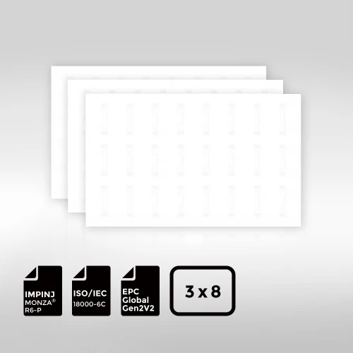
BioPoly™ Vinyl RFID Inlay Sheet Impinj® Monza® R6-P

The Impinj® Monza® R6-P BioPoly™ Vinyl RFID Inlay features the high-performance Monza® R6-P chip, known for its exceptional read range, reliability, and accuracy. This chip optimizes inventory and asset tracking, ensuring fast and efficient data capture in various applications. While offering cutting-edge RFID technology, the inlay also utilizes eco-friendly BioPoly™ Vinyl, a biodegradable PVC made with renewable materials that degrades within three years, reducing environmental impact without compromising performance. The combination of the Monza® R6-P chip and sustainable BioPoly™ Vinyl makes this inlay a powerful, environmentally responsible solution for modern RFID needs.